Dissolved Air Flotation (DAF) VLT Series Systems
Dissolved Air Floatation is widely used for separating solids, fats, oil, and grease from a waste stream. In the process, pressurized water is saturated with dissolved air and is discharged into a flotation vessel. The microscopic air bubbles attach to solids and float them to the surface, forming a sludge blanket. A scraping assembly skims the sludge off the surface of the water and into a sump. From the sump, sludge is pumped to dewatering equipment. The treated water flows from the DAF vessel for discharge or on to other treatment processes. Click the image to the right to view a video of a VLT-Series Dissolved Air Flotation system in operation.
Why should I select a VLT-Series DAF?
The VLT-Series DAF system is engineered to address the inefficiencies common to other system designs. We incorporated a V-shaped flotation cell with a sludge auger so any solids that resist flotation can be automatically removed from the base of the vessel. The skimmer assembly is made of materials that don't scale, foul, or corrode. The adjustable weir and scraper assembly assures that there are never any dead zones or carry overs in the sludge skimming zone. With the addition of the new Lamella Tubes the effective surface area of the DAF has increased substantially, doubling the flow rate for an small footprint, with clearer effluent water. As a result, the VLT-Series can achieve up to 99% removal of TSS, FOG and 75% of BOD. Dissolved Air Flotation systems pair well with flocculation tubes, chemical reaction tanks, and chemical feed systems.
Industries/Applications perfectly suited to a dissolved air flotation unit
- Meat processing / slaughterhouse (beef, pigs, sheep, goats)
- Ice Cream factory
- Poultry processing (chickens, turkey, duck, geese)
- Confectionary/Candy manufacturing
- Bakery / baked goods
- Oil & Gas industry
- Mining industry
- Automotive industry
- Printing manufacturer (ink removal from wastewater)
- Cereal and snack foods
- Food processing and packaging
- Dairy processing (milk, cheese, yogurt)
- Beverage factories (breweries, juice, soda)
- Paper and pulp industry
- Metal plating and finishing
- Biochemical industry
- Recycling of glass, plastics, paper
- Egg processing
How a dissolved air flotation (DAF) system works
A recirculation loop of pressurized water is saturated with dissolved air using a multistage impeller pump. The product of this process is now termed “whitewater”. The whitewater is then discharged into the influent pipe and DAF vessel. Microscopic air bubbles attach themselves to the flocculated sludge particles causing them to rise to the surface to form a sludge blanket. As the sludge blanket thickens, a scrapper mechanism transfers the sludge to the DAF sludge compartment. From there, the sludge is pumped into an outside sludge holding tank and finally to dewatering equipment. Ecologix VLT-Series Dissolved Air Flotation (DAF) systems are highly efficient at removing contaminants from wastewater. They achieve superior results at higher flow and contaminant loadings than can be achieved by other conventional gravity separation systems. Our revolutionary V-shaped design in combination with Lamella Tubes (Inclined Tubes) remove up to 99% of TSS/FOG and up to 75% of BOD loadings. Our proprietary design produces an unsurpassed dissolved air-to-solids ratio and clarifies polluted water with unmatched performance.


VLT Series DAF available models
| VLT-405 | ||||||||
|---|---|---|---|---|---|---|---|---|
| Model | Flow Rate US gpm |
Flow Rate m3/h |
Dimensions (Ft) (L x W x H) |
Dimensions (m) (L x W x H) |
Surface Area (Ft2) |
Surface Area (m2) |
Power (hp) |
Design |
| VLT-405 | 75 | 17 | 4' 4" x 4' x 8' | 1.3 x 1.2 x 2.4 | 120 | 11 | 8.0 | |
| ACE-405 | 120 | 31 | 4' 4" x 4' x 8' | 1.3 x 1.2 x 2.4 | 120 | 11 | 31.0 | |

| VLT 4 Series | ||||||||
|---|---|---|---|---|---|---|---|---|
| Model | Flow Rate US gpm |
Flow Rate m3/h |
Dimensions (Ft) (L x W x H) |
Dimensions (m) (L x W x H) |
Surface Area (Ft2) |
Surface Area (m2) |
Power (hp) |
Design |
| VLT-410 | 150 | 34 | 12' 7" x 5' 5" x 9' | 4 x 1.6 x 2.7 | 235 | 22 | 11.0 | |
| VLT-415 | 275 | 60 | 16' 9" x 5' 5" x 9' | 5 x 1.6 x 2.7 | 400 | 40 | 21.0 | |
| VLT-420 | 400 | 90 | 21' 9" x 5' 5" x 9' | 6.6 x 1.6 x 2.7 | 600 | 60 | 21.0 | |
| VLT-425 | 500 | 115 | 27' x 5' 5" x 9' | 8.1 x 1.6 x 2.7 | 800 | 75 | 31.0 | |
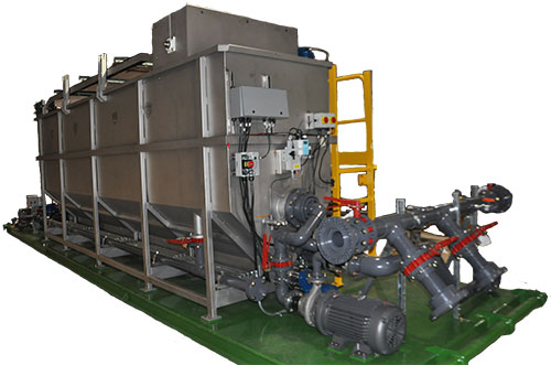
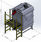
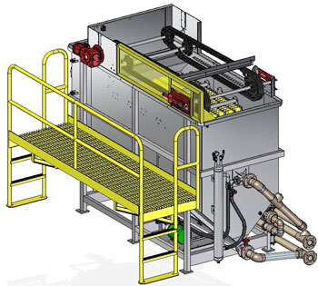
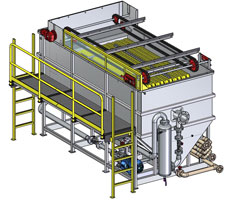
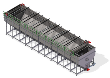
Ecologix VLT-420 DAF
| VLT 7 Series | ||||||||
|---|---|---|---|---|---|---|---|---|
| Model | Flow Rate US gpm |
Flow Rate m3/h |
Dimensions (Ft) (L x W x H) |
Dimensions (m) (L x W x H) |
Surface Area (Ft2) |
Surface Area (m2) |
Power (hp) |
Design |
| VLT-715 | 500 | 113 | 16' 9" x 8' 5" x 10' 5" | 5 x 2.6 x 3.1 | 715 | 66 | 31.0 | |
| VLT-720 | 700 | 160 | 21' 9" x 8' 5" x 10' 5" | 6.7 x 2.6 x 3.1 | 1060 | 100 | 31.0 | |
| VLT-725 | 900 | 200 | 26' 9" x 8' 5" x 10' 5" | 8.1 x 2.6 x 3.1 | 1400 | 130 | 31.5 | |
| VLT-730 | 1100 | 250 | 31' 9" x 8' 5" x 10' 5" | 9.7 x 2.6 x 3.1 | 1750 | 160 | 61.5 | |
| VLT 10 Series | ||||||||
|---|---|---|---|---|---|---|---|---|
| Model | Flow Rate US gpm |
Flow Rate m3/h |
Dimensions (Ft) (L x W x H) |
Dimensions (m) (L x W x H) |
Surface Area (Ft2) |
Surface Area (m2) |
Power (hp) |
Design |
| VLT-1025 | 1300 | 295 | 27' 9" X 11' 5" x 11' | 8.4 x 3.5 x 3.3 | 1900 | 175 | 62.5 | |
| VLT-1030 | 1600 | 363 | 32' 9" X 11' 5" x 11' | 10 x 3.5 x 3.3 | 2400 | 220 | 92.5 | |
| VLT-1035 | 1900 | 430 | 37' 9" X 11' 5" x 11' | 11.5 x 3.5 x 3.3 | 2900 | 270 | 93.0 | |
| VLT-1040 | 2200 | 500 | 42' 9" X 11' 5" x 11' | 13 x 3.5 x 3.3 | 3395 | 315 | 93.5 | |
| VLT-1045 | 2500 | 568 | 47' 9" X 11' 5" x 11' | 14.5 x 3.5 x 3.3 | 3890 | 360 | 123.5 | |
| VLT-1050 | 2800 | 635 | 52' 9" X 11' 5" x 11' | 16 x 3.5 x 3.3 | 4385 | 400 | 123.5 | |
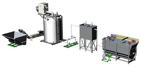
Meat Processing Plant
This system includes coarse screening, chemical reaction tanks, DAF unit, and screenings/sludge dewatering. Designed to remove TSS, FOG, and BOD.
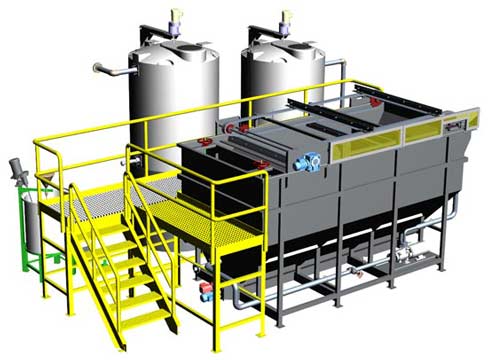
Dairy Plant
This process includes high flow, gravity fed chemical reaction tanks, DAF unit, and chemical feed systems. Designed to reduce TSS, FOG, and BOD.
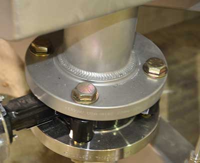
Highest Quality Manufacturing Standards
All our equipment is manufactured using rigorous design and operating standards right down to every weld and every component that we use. Review below some of our workmanship.
Specifications for Dissolved Air Flotation System Download Specifications
Ecologix Environmental Systems, LLC shall supply the VLT Series Dissolved Air Flotation (DAF) system that shall include influent, effluent, and drain connections, floatation tank, contact chamber, float removal system, settled solids return system, lamella tubes, complete recirculation system including whitewater pump, saturation tank followed by a secondary weir for finer bubble separation of large bubbles from small bubbles and local PLC based control panel. As more specifically outlined below:
a) Influent Wastewater: Influent is induced with chemistry in order to precipitate suspended solids, fat oil & grease and other impurities from the water prior to the physical separation with dissolved air flotation.
The DAF shall incorporate one of the following methodologies to inject and mix chemicals:
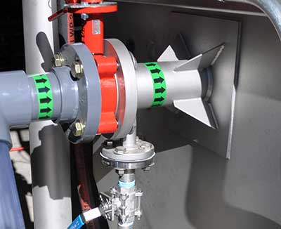
- Flocculation Tubes: The DAF shall incorporate flocculation tubes made of Schedule 80 PVC with injection ports for coagulants, pH adjustment and polymers, along with static mixers. The wastewater shall enter the flocculation tubes through a flanged connector and exit into the contact tank through another flanged connector at the header.
- Chemical Reaction Tanks: For greater control over the precipitation of impurities, chemical reaction tanks are recommended. The reaction tanks shall have mounted mixers with VFDs (Variable Frequency Drives) and means to accept chemistry from various chemical feed pumps into the tanks. The reaction tanks shall be placed prior to the DAF. The influent wastewater shall first pass through the reaction tanks and then exit into the contact chamber through a flange connector at the header.
b) Contact Chamber: The influent wastewater shall enter the DAF unit through a flanged influent header into the contact chamber. Simultaneously, the recycle (whitewater) stream shall be mixed with the influent wastewater through a tangential pipe that is connected into the header, creating vortex. The vortex effect results in 100% contact between the air bubbles in the whitewater and the dirty influent water. As the water enters into the contact chamber it shall first encounter an internal weir acting as a secondary coarse bubble separator which provides even distribution and mixing of the process flow across the width of the unit, without any turbulence. The contact chamber has a drain port for removal of heavy solids that may settle in the chamber.
c) Flotation Tank: The unit consists of a rectangular flotation tank constructed of 304 stainless steel plate reinforced with 304 stainless steel tubular vertical wall structural supports.
- The vessel shall be supported on a stainless steel base consisting of vertical and horizontal beams across the width and length of the unit.
- The vessel shall be constructed to allow for easy cleaning around and under the unit. The unit shall be designed for above-ground positioning on a suitable concrete pad or steel frame and shall be constructed for indoor or outdoor conditions.
d) Lamella Tubes in Flotation Chamber: To increase efficiency and maintain smaller footprint, the Flotation Chamber shall be filled with Lamella Tubes, whose function is to increase the projected surface area and improve the separation efficiency of the solids from the clear water. The Lamella Tubes shall be made of Polypropylene material with 60° angular slant toward the co-current water flow. The lamella tubes shall have chevron shape to prevent clogging and 2” spacing between each lamella.
e) Float Removal System: The unit shall be equipped with a chain and flight skimmers to remove top floats, driven by a low speed VFD (Variable Frequency Drive), gear reducer with motor assembly. The float material shall be removed in a co-current direction. This design involves moving the float bed on the surface down the length of the unit to a separate compartment in the direction of flow and allows for longer float residence time prior to removal, resulting in drier float material.
- The top skimmer system consists of non-metallic glass reinforced nylon chain with a maximum recommended working load of 1740 lbs., or average ultimate strength of 2800 lbs. in a double pitch roller chain. The skimmer blades are spaced approximately every 6 ft. along the chain length. The chain system operates on single duty, non-metallic UHMW sprockets mounted on stainless steel shafts turning in adjustable bearing supports. The system is driven by a gear drive with TEFC coupled to the keyed drive shaft. Drive speed shall be controlled by a VFD (in the control panel) which shall be equipped with a shaft power monitor to protect the equipment in case of overload. Adjustable timer controls or PLC controls (in optional control panel) provide for intermittent skimmer operation which allows for flexibility in the removal of float material from the unit.
- On the effluent end, the skimmer pulls the collected surface material (float) up an inclined beach plate and into an internal float hopper. The beach is sloped to allow for efficient removal of float material by the skimmer wiper. The internal float hopper is sized to allow intermediate storage of the material prior to discharge through a flanged pipe for pumping to storage for dewatering or transport.
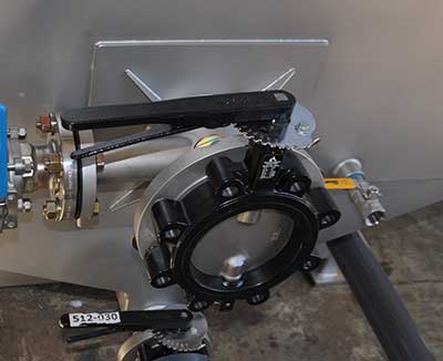
f) Settled Solids Removal System: Full-length sloped side walls channel shall concentrate settable material to a trough in the bottom of the tank for removal by an auger system pulling the material towards the influent end of the unit (counter-current). The counter-current design removes settled material quickly from the unit at the opposite end from the treated water discharge. The material is discharged through a flanged pipe located in the influent end of the unit base. The auger system consists of a 4” or 6" diameter, with a 4” or 6” pitch. The 304 stainless steel auger shall be located at the bottom of the V-shaped side walls. The auger shall extend 95% to 100% of the full length of the DAF. The system shall be driven by a heavy duty gear drive assembly connected to a 0.33HP/460V/TEFC motor with a shear coupling for overload protection. Adjustable timer controls (in optional control panel) provide for intermittent auger operation which allows for flexibility in the removal of bottom material from the unit.
g) Effluent Discharge: At the effluent the clear water shall flow under the sludge compartment, over a couple of weirs and into a clear well compartment from where it shall be discharged through a flanged pipe. The system shall have two weirs on opposite sides of the DAF to promote symmetric flow across the unit.
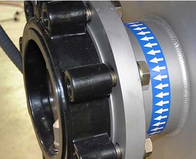
h) Recirculation (Whitewater) System: The recirculation system is designed to saturate, under pressure, a clarified effluent stream with air to create a dissolved air solution or whitewater. When the whitewater stream is introduced into the contact chamber of the DAF unit, the fine, micro and nano-bubbles are then released to attach themselves to the flocculated suspended solids, causing it to rise to the surface of the water within the flotation tank for further removal as sludge.
- Clarified wastewater from the effluent discharge is recycled through the unit by a centrifugal DAF pump designed to operate at pressures in the range of 80-120 psi. The pump features a 316 stainless steel casing and impeller, stainless steel shaft, and a premium efficiency 460 V/3 ph/60 Hz/TEFC motor.
- Air is supplied into the recycle stream via a suction port on the whitewater pump intake, drawing in either ambient or compressed air and forcing it into solution with the recycle stream under pressure from the pump. Air flow into the pump is regulated by an air rotameter with a needle valve. All plastic recirculation piping is Sch. 80 PVC.
- The recycle stream is routed through a Saturation Tank that provides additional hydraulic retention time under pressure and allows the separation and removal of large, undissolved air bubbles. The Saturation Tank shall be a vertical section of stainless steel pipe in the recycle piping system that is equipped with a bottom valve for draining and servicing. Liquid level in the Saturation Tank shall automatically be maintained by an air release valve with an in-line equalizer.
- Discharge pressure from the recycle pump and the Saturation Tank shall be channeled through a tangential pipe and into the influent pipe causing vortex to take effect to maximize the contact of the air bubbles with the incoming suspended solids prior to entering the contact chamber.
- A secondary bubble separation chamber shall be positioned immediately after the influent pipe and prior to the contact chamber for further separation of large bubble, to ensure maximum consistency of small air bubble size and to eliminate any possible turbulence within the contact chamber.
- A mid-tank whitewater injection system shall be optionally provided when the length of the DAF exceeds certain dimensions and when the suspended solids are above certain range. A liquid filled pressure gauge is provided for monitoring recycle pressurization performance.
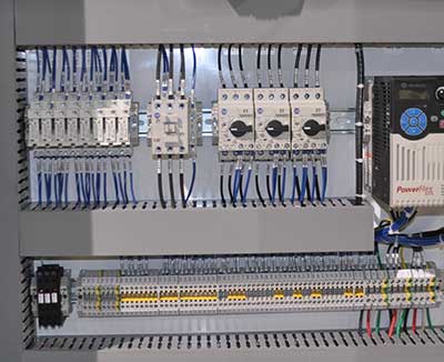
i) Control Panel: The controls shall be housed in a minimum of NEMA 4/12 enclosure unless environmental conditions, such as outdoor placement or explosion proof require otherwise.
- The DAF shall be PLC controlled with a color touchscreen interface including graphics, text, and the ability for the operator to change the required parameters for maximum efficiently.
- The control panel shall be designed to protect all field equipment and allow for individual equipment electrical isolation.
- The control panel shall include the ability to automatically send out alarms to the required personnel such as maintenance. It shall also have the ability to send out reports to the required personnel such as production or management.
- The PLC shall have the ability to simultaneously communicate with the customer SCADA system, regardless of the standard type and protocol that may be used by the client.
j) Paint and Coatings: All motors, pumps, drives, instruments, control panels, and valves are shipped with the manufacturer's standard coatings.